


 |
Mini 3-D/3-CH Digital Weight Indicator For 1-3 Channels Force Measuring System
Product Details:
| Place of Origin: | China |
| Brand Name: | Supmeter |
| Certification: | CE |
| Model Number: | BST106-B60[R] |
Payment & Shipping Terms:
| Minimum Order Quantity: | 1pcs |
|---|---|
| Price: | Negotiation |
| Packaging Details: | 1pcs/box |
| Payment Terms: | T/T, Western Union |
|
Detail Information |
|||
| Power Supply: | DC24V | DI: | 4 |
|---|---|---|---|
| DO: | 2 | Outline Size: | 107*60*100mm |
| Highlight: | electronic weight indicator,digital load controller |
||
Product Description
Mini 3-D/3-CH Force Measuring Controller Electronic Weighing Indicator For 1-3 Channels Force Measuring System
Technical Specification
- Executing Standard
- CMC GB/T 7724-2008PRC National Standard.
- OMIL R76: 2006International Recommendation.
- Accuracy Grade: III.
- Verification Accuracy: 0.03%.
- Static Force Measuring Accuracy: 0.2%~0.5%.
- Display
- 2×16 LCD display screen with white LED background for English/Digit display.
- Channel X/Y/Z Force Value Display Range: -5000~+5000.
- Resultant Force Display Range: 0~9999.
- Channel X/Y/Z Force Capacity: Setting Range 1~5000.
- Scale Division: Optional 1, 2, 5, 10, 20, 50, 100, 200, 500.
- Display Resolution: 1/5000.
- Force Value Unit: Optional kg, t, g, N, kN, none.
- Decimal Point: Optional 0, 0.0, 0.00, 0.000.
- Display Refreshing Time: Setting Range 0.01~1.00s.
- Kaypad
- 4-key keypad for shortcut operation.
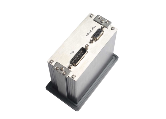
- Channel X/Y/Z Loadcell Interface
- Excitation Voltage/Max. Current: DC5V/120mA [4-350Ω loadcells].
- Signal Input Range: ±35mV.
- Output Sensitivity of Loadcell: 1.0~7.0mV/V.
- 24-bit ∑-△ADC with internal resolution 1/1,000,000.
- Sampling Frequency: 1280Hz.
- Zero Drift: ±0.1μV/℃ RTI (Relative to Input).
- Gain Drift: ±5ppm/℃.
- Non-linearity: 0.005%FS.
- Switch Signal Interface
- 4 Normally Open Switch Inputs [DI].
- 2 Transistor Switch Outputs [DO] for Real-time Resultant Force or Resultant Force Peak Value Upper/Lower Limit Alarm.
- The Contact of Transistor Switches can be defined as ‘Normally Open’ or ‘Normally Closed’.
- Contact Capacity of Transistor Switch: DC24V, 10mA.
- Digital Communication Interface
- COM1: Fixed configuration RS485&RS232. Free to select one of them via internal DIP switch.
- Connectable: Host IPC/PLC and LED Remote Display.
Operating Specification
- Operating Voltage: DC24V±20%.
- Max. Power Consumption: 5W.
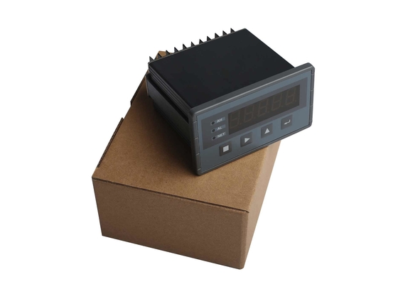
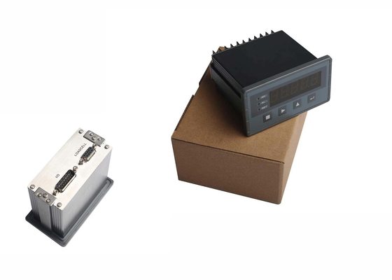
- Outline Size: 107×60×100mm [W×H×D].
- Panel Cut-out Size: 94×47 mm [W×H].
- Operating Temperature: -10℃ to +40℃.
- Storage Temperature: -30℃ to +60℃.
- Relative Humidity: Max. 85%RH.
- Protection Level of Front Panel: IP65.
- Weight: Approx. 0.25kg.
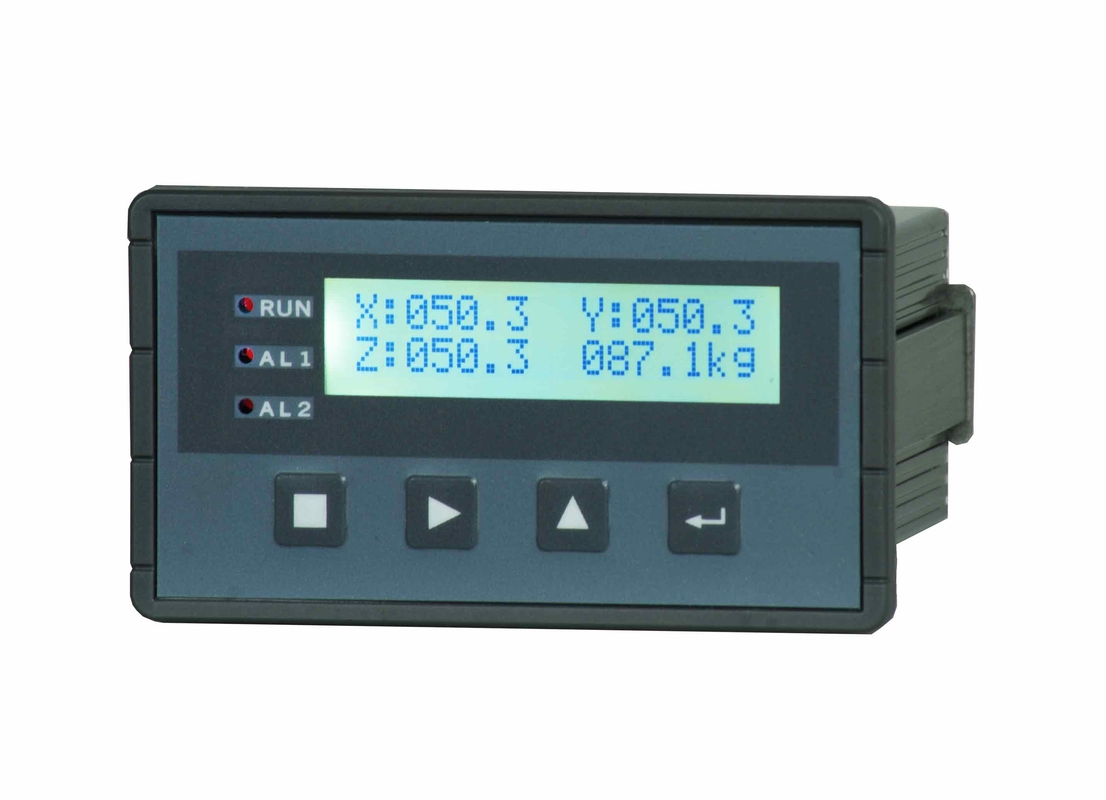
Pictures
![]()
![]()
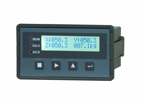
Data Display
| Name | Description | Range | Note |
| X |
Channel X Real-time Force Value or Peak Value. |
-5000~+5000 | Refer to Parameters [202]~[207]. |
| Y |
Channel Y Real-time Force Value or Peak Value. |
-5000~+5000 | |
| Z |
Channel Z Real-time Force Value or Peak Value. |
-5000~+5000 | |
| [F] | Real-time Resultant Force or Resultant Force Peak Value [Force Value Unit]. |
3-D Algorithm: F2 = X2 + Y2 + Z2 CUSUM Algorithm: F = X + Y + Z |
Alarm Sign
| Sign | Alarm Cause | Solution |
| AD_ER | ADC Failure. | Replace the ADC module. |
| OV_AD | Over ADC Range. |
Force signal exceeds A/D conversion range. 1. Check if the loadcell is connected. 2. Check if the capacity of loadcell is too small. 3. Check if the loading force is too big. |
| OV_LD | Force Value Overload Alarm. |
Force Value>(Single-channel Force Capacity+9×Scale Division). 1. Check if the loadcell is connected. 2. Check if the capacity of loadcell is too small. 3. Check if the loading force is too big. Refer to Parameter [102]. |
| Resultant Force Overload Alarm. |
Resultant Force>(Max. Resultant Force+9×Scale Division). Refer to Parameter [102]. |
State Indication
| LED light | Description |
| [RUN] |
OFF: Real-time Force Value tracking display state. ON: Peak Value Detecting Result holding display state [Peak Value Detecting Process Finished]. Blinking: Peak Value tracking display state [In Peak Value Detecting Process]. |
| [AL1] |
Real-time Resultant Force or Resultant Force Peak Value Upper Limit Alarm. Refer to Parameters [200]&[202]. |
| [AL2] |
Real-time Resultant Force or Resultant Force Peak Value Lower Limit Alarm. Refer to Parameters [201]&[202]. |
Installation