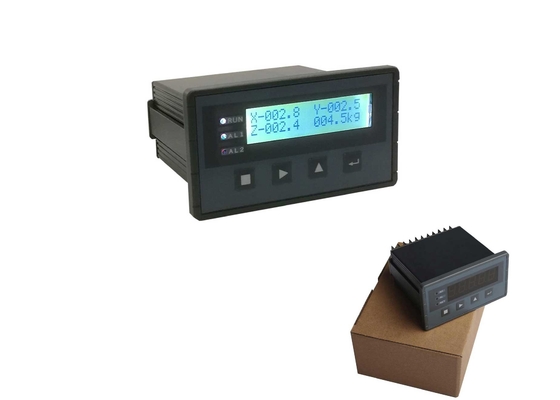
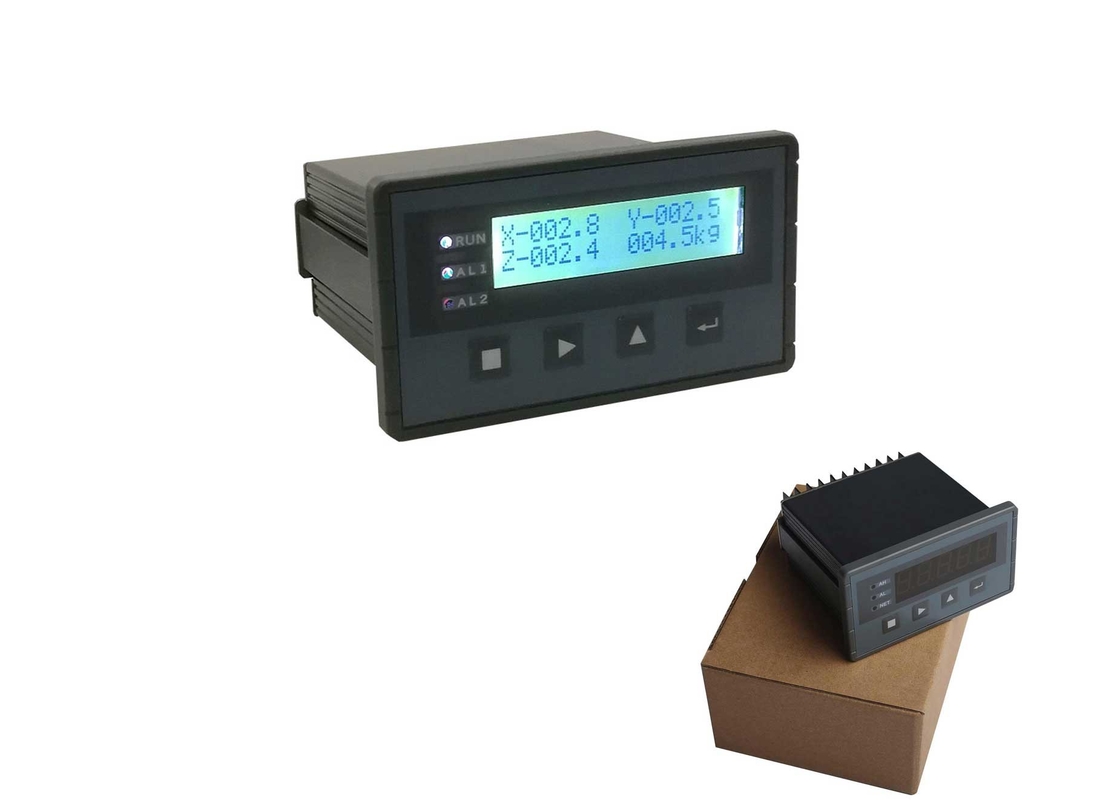
Durable Mini 3- D /3- Channels Force Measuring Controller BST106-B60R( F )
Product Details:
| Place of Origin: | China |
| Brand Name: | SUPMETER |
| Certification: | CE |
| Model Number: | BST106-B60R[F] |
Payment & Shipping Terms:
| Minimum Order Quantity: | 10pcs |
|---|---|
| Price: | negotiating |
| Packaging Details: | caton box |
| Delivery Time: | 5-15 working day |
| Payment Terms: | T/T, Western Union |
| Supply Ability: | 500pcs/month |
|
Detail Information |
|||
| Power Supply: | DC24V | Warranty: | 1 Year / 12 Months |
|---|---|---|---|
| Display: | LCD | ||
| Highlight: | electronic weight indicator,digital load controller |
||
Product Description
Durable Mini 3- D /3- Channels Force Measuring Controller BST106-B60R( F )
Main Features:
² Main Applications: 3-Channel Real-time Force Values & Real-time Resultant Force Display, 3-Channel Force Peak Values & Resultant Force Peak Value Display, Real-time Resultant Force or Resultant Force Peak Value Upper/Lower Limit DO Alarm, RS232/RS485 Digit Transmission.
² Optional Resultant Force [F] Algorithms: 3-D Algorithm [F2=X2+Y2+Z2] and CUSUM [Cumulative Sum] Algorithm [F=X+Y+Z].
² X&Y&Z sampling channels can be opened and closed via setting the related parameters for 1-Channel, 2-Channel and 3-Channel Force Measuring.
² Optional Force-Measuring Modes: ‘Real-time Value Display&Alarm Mode’ and ‘Peak Value Display&Alarm Mode’.
² DO output can used for ‘Real-time Resultant Force Alarm’ or ‘Resultant Force Peak Value Alarm’.
² Optional ‘Auto Enter Peak&Valley Value Detecting Process after Power-on’ function.
² EMC design with high anti-jamming capability, suitable for industrial environment.
² 32-bit ARM CPU with 48MHz clock & higher arithmetic speed.
² 2×16 LCD display screen with white LED background for English/Digit display.
² 24-bit High-precision and high-speed ∑-A/D conversion module with 1/1,000,000 internal resolution and samplingfrequency 1280Hz.
² Special anti-vibration digital filtering algorithm for ensuring the force measuring stability and accuracy when there is strong vibration on the load receptor, and the rapid response capability when the force signal changes.
² Max. Connection Quantity: 8 Loadcells (350Ω).
² Zero Calibration, Load Calibration and Data Calibration functions available.
² Digital Setting&Calibration and I/O Testing functions available.
² 4 Normally open switch inputs [DI] and 2 normally open/closed transistor switch outputs [DO].
² Optional RS232 or RS485 communication port for connecting Host IPC/PLC and LED Remote Display.
² With the multitasking mode, the processes of weighing, alarm output and signal transmission will not be interrupted by parameter setting and the other operations.
Operation Interface Diagram
Data Display
| Name | Description | Range | Note |
| X |
Channel X Real-time Force Value or Peak Value. |
-5000~+5000 | Refer to Parameters [202]~[207]. |
| Y |
Channel Y Real-time Force Value or Peak Value. |
-5000~+5000 | |
| Z |
Channel Z Real-time Force Value or Peak Value. |
-5000~+5000 | |
| [F] | Real-time Resultant Force or Resultant Force Peak Value [Force Value Unit]. |
3-D Algorithm: F2 = X2 + Y2 + Z2 CUSUM Algorithm: F = X + Y + Z |
Alarm Sign
| Sign | Alarm Cause | Solution |
| AD_ER | ADC Failure. | Replace the ADC module. |
| OV_AD | Over ADC Range. |
Force signal exceeds A/D conversion range. 1. Check if the loadcell is connected. 2. Check if the capacity of loadcell is too small. 3. Check if the loading force is too big. |
| OV_LD | Force Value Overload Alarm. |
Force Value>(Single-channel Force Capacity+9×Scale Division). 1. Check if the loadcell is connected. 2. Check if the capacity of loadcell is too small. 3. Check if the loading force is too big. Refer to Parameter [102]. |
| ResultantForce Overload Alarm. |
Resultant Force>(Max. Resultant Force+9×Scale Division). Refer to Parameter [102]. |
Installation
![]()


