


 |
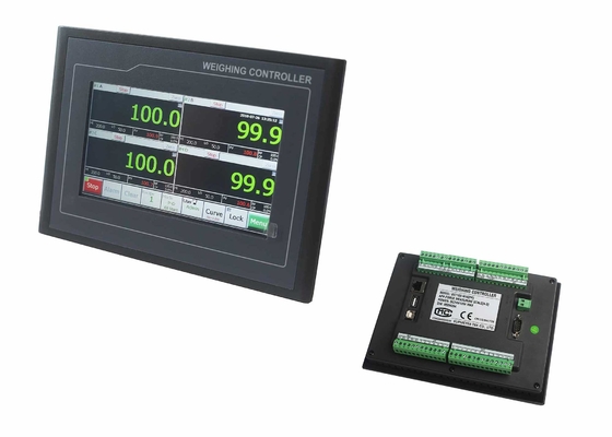
24V Load Cell Display And Controller For Positive Negative Direction Peak Value Detection
Product Details:
| Place of Origin: | China |
| Brand Name: | Supmeter |
| Certification: | CE |
| Model Number: | BST106-M10[FF] |
Payment & Shipping Terms:
| Minimum Order Quantity: | 1pcs |
|---|---|
| Price: | Negotiation |
| Packaging Details: | 1pcs/box |
| Delivery Time: | 3-10 working days |
| Payment Terms: | T/T, Western Union |
| Supply Ability: | 10000pcs per month |
|
Detail Information |
|||
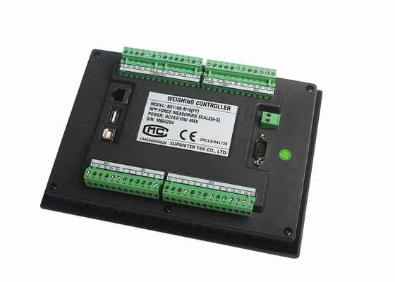
| Power Supply: | DC24V | Max. Connect: | 16Loadcells[350Ω] |
|---|---|---|---|
| Input: | 7DIs | Output: | 18DOs |
| COM@COM1: | RS232 | COM2: | RS485 |
| Highlight: | programmable load cell controller,load cell indicator |
||
Product Description
1-4 Channels Force Measuring Controller For Positive&Negative Direction Peak Value Detection
Main Features:
- EMC design with high anti-jam for industrial environment.
- DC24V power input with reverse polarity protection.
- Cortex-A8 CPU with 600MHz Clock, 128M Flash.
- 7” [800×480] or 10.2” [1024×600] TFT touch panel.
- 24-bit ∑-△ADC with internal resolution 1/130,000.
- High sampling frequency 3200Hz.
- Auto Zero Tracking.
- Positive/Negative Segmenting Span Correction.
- Save detection results for query automatically.
- Save real-time curve into U-disk automatically.
- Definable DI/DO/AO/COM[Communication Port].
- Recipe Number: 100.
Technical Specification:
| Power Supply | DC24V±20%,Max.10w. |
| Display | HMI |
| Sampling Frequency | 600Hz |
| A/D Convert | 24-bit |
| LAN | Optional Ethernet |
| USB1 | Connect mouse, software download, data backup |
| Max. Connection number of Loadcell |
16Loadcells (350Ω) |
| DI | 7 Normally Open Switch Inputs |
| DO | 18 Normally Open Transistor Switch Outputs |
| AO | 4Analog Signal Output: 4~20mA. |
| Operating Temperature | -25℃~+45℃ |
| Verification Accuracy | 0.02% |
| Batching Accuracy | 0.2%~0.5% |
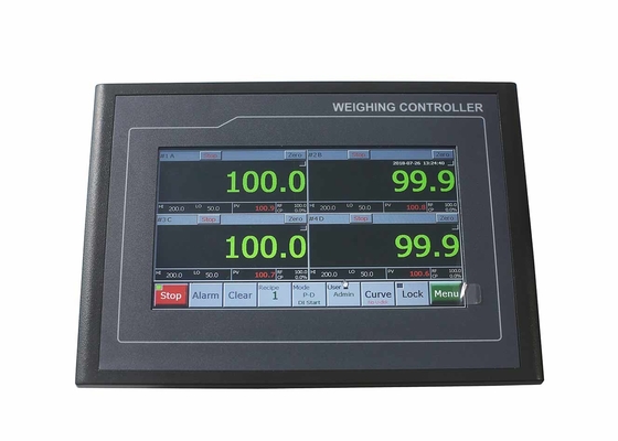
Main Operation Interface for APP1 Single-scale Mode
![]()
![]()
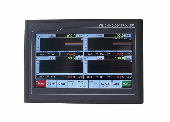
Main Operation Interface for APP2 Four-scale Mode
![]()
![]()
Button Operation
| Name | Operation | State Indicator | Authorization |
|
【Start】 【Stop】 |
Start/Stop Peak Detection Process. |
Green: Running state. Grey: Stop state. |
All Users |
| 【Menu】 | Enter Main Menu. | ||
| 【Lock】 |
Screen-locking: Locking/unlocking the operating buttons of main display interface. Auto Screen-locking: Refer to parameter [901]. |
Flashing Red: Locked. Grey: Unlocked. |
|
| 【User】 | User Login. Display: Operator / Engineer / Admin. | ||
| [Recipe] | ‘Working Recipe No.’ Setting. | ||
| 【Clear】 | Clear Screen. | ||
| 【Alarm】 | Clear Alarm. | ||
| 【Zero】 | Zero Fine Adjustment [No Power-down Protection]. | ||
| 【Curve】 | ‘Curve Window Property’ Setting. |
Engineer Administrator |
|
| 【Mode】 |
‘Working Mode’ Setting. Refer ‘6.3.3 Working Mode Parameters’. |
Data Display & Quick Setting
| Name | Description | Authorization |
| Green Digits | Real-time Force Value. | |
| Curve Window | Display in Peak Detection Process: Green Real-time Force Value Curve, Red Positive Direction High/Low Limit Straight Line and Pink Negative Direction High/Low Limit Straight Line. | |
| 【Zoom】Operation. | All Users | |
| [#1/#2/#3/#4] | Channel No.. | |
| [A/B/C/D] | Channel Name. | |
| [RF] | Reference Value. | |
| [CP] |
Comparison Value. CP=(Real-time Force Value-Reference Value)/ Reference Value × 100% |
|
| [HI] | High Limit Value. | |
| [LO] | Low Limit Value. | |
| [NV] | Negative Direction Peak Value. | |
| [PV] | Positive Direction Peak Value. | |
| [▲] | High Limit Alarm. | |
| [▼] | Low Limit Alarm. | |
| [Date&Time] | Date&Time. |
1-4 Channels Force Measuring Controller For Positive&Negative Direction Peak Value Detection
![]()
Outline Size
![]()
Installation Mode
![]()
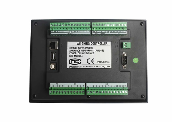
Terminal Diagram
![]()